
Introduction
This project came from a fairly fun client request: make a VR experience feel more immersive by adding physical feedback to the seat. The idea was simple enough to understand, but the electronics turned into a little adventure. The client was already giving people the usual visual immersion with VR goggles and the vibration from a controller, but he wanted something more. He wanted the whole seat to shake in sync with the game, so the experience would feel much more real.
That meant there were two problems to solve. The first was figuring out how to read the rumble signal from an Xbox controller, and the second was figuring out how to drive a very old and very strange vibration actuator that was not exactly designed to be controlled by a modern microcontroller.
Hacking the controller
The controller I used was an Xbox One pad, and the vibration came from two rumble motors inside it. I started by probing the signal with an oscilloscope, and it turned out to be the old reliable PWM. That meant I could read it in real time with an Arduino using the pulseIn() function and then send it somewhere else.
To carry the signal to the seat setup, I used an NRF24 module. The whole thing was packed into a small PCB, powered by a 9V battery, and placed into a 3D printed enclosure that fit neatly onto the back of the controller where the battery cover normally sits. It was a very satisfying moment when that part finally worked.
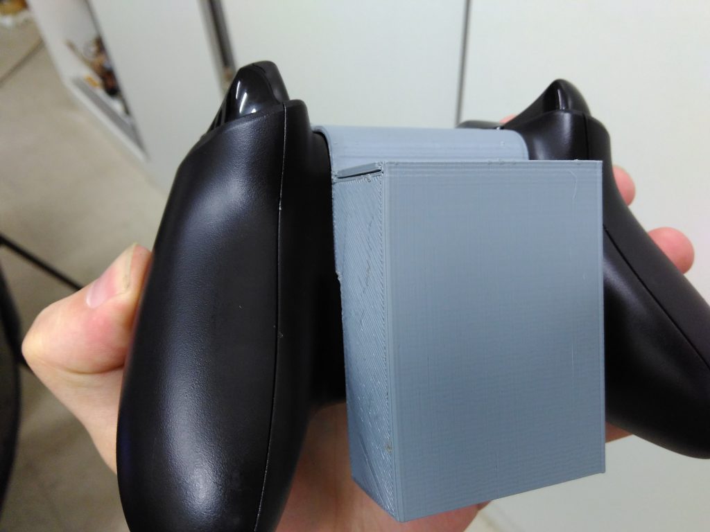
3D printed enclosure
Investigating the actuator
The actuator itself was an old back massager, which was both exciting and a little suspicious. It was a large plastic box connected through an RJ9 cable to a knob that looked like a potentiometer, but it was sealed shut, so I could not open it without risking the whole thing. I probed the terminals with a multimeter and concluded that it was probably being controlled by a simple variable resistor.
That led to the obvious next step: mimic that potentiometer digitally. A digital potentiometer seemed like the right answer on paper, but then I measured the voltage and current and realized the device was actually being controlled through 110V AC mains power. That made the standard solution useless. I had to think outside the box, and the result was a custom high-voltage digital potentiometer built from TRIACs and optocouplers.
AC voltage Digital potentiometer design
The basic concept behind a digital potentiometer is not complicated. You have a chain of resistors, and a switch selects where the wiper sits along that chain. In this case, I needed to switch AC rather than low-voltage DC, so I replaced the usual transistor-based approach with TRIACs. The TRIACs were triggered by optocouplers controlled by an Arduino, which let me drive the actuator in a way that was both practical and surprisingly elegant.
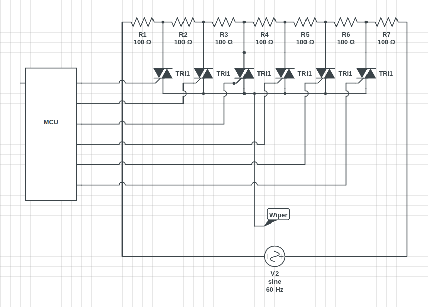
High abstraction level schematic of the proposed solution
Integrating the system
Once both pieces were working, it was just a matter of connecting them together. One Arduino was reading the controller data and sending it over NRF24, while another Arduino received that information and used it to control the custom high-voltage digital potentiometer. The actuator was connected through the RJ9 cable, and then it was time to see whether the whole thing would actually behave the way I wanted.
Results
A few small bugs and a couple of short circuits later, everything came together. The system worked, the client was happy, and the whole thing felt like one of those projects that starts with a weird idea and somehow turns into a real piece of hardware. The video below shows it in action.
System being tested
Comments
Comment with your GitHub account.